
G series · Underwater reconnaissance gliders · Concept design
Underwater Reconnaissance Gliders and Acoustic Identification Module
Three complete concept designs: hull, buoyancy engine, attitude control, navigation, communications, power and payload, laid out in 3D. Mass, centre of buoyancy and centre of gravity come straight from each 3D model, trimmed to neutral buoyancy with zero part interference; performance figures are estimates derived from the model.
- Status
- Concept design (unverified)
- Axes
- X along the hull, nose toward −X; Z up; +Y starboard
- Units
- mm, kg; seawater 1025 kg/m³
- Navigation scope
- Hardware architecture and mounting only; no software, no specific modules
- Depth
- Design targets only, not pressure ratings
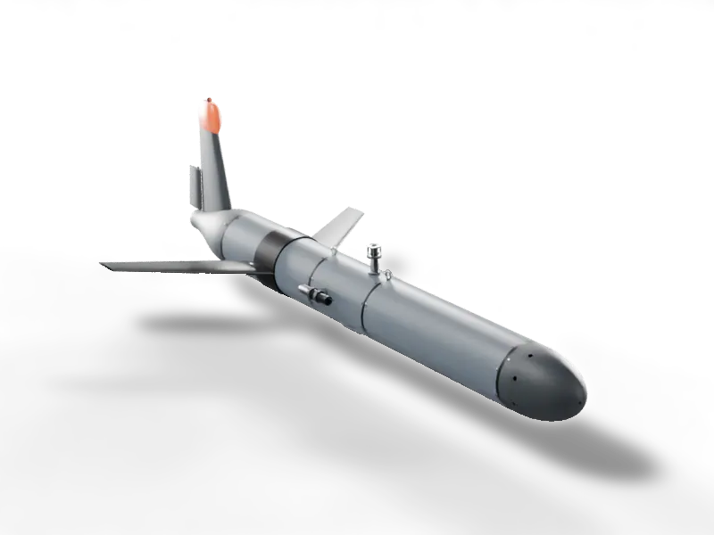
Loading turntable frames…
Long, quiet listening near shore and on the continental shelf: low cost, deployable in numbers
Long-duration covert reconnaissance in coastal and shelf waters: passive acoustic monitoring (ship noise) plus CTD profiles, surfacing every 1–3 hours to report by satellite and correct position. A single pressure hull in three sections; the buoyancy engine is a piston cylinder in the nose, pitch comes from moving the battery and steering from a rudder. No propeller, so self-noise is low.
Endurance
66days
150 m profiles, 1.1 h per cycle
Range
1,330km
Horizontal speed 0.26 m/s
Energy per km
2.9Wh
Average power 2.4 W
Max lift-to-drag
5.8
Min glide angle 10°
- Configuration
- Single torpedo hull + 40° swept wing + antenna fin + rudder
- Length × span × height
- 2,222 × 1,120 × 636 mm
- Mass in air / displacement
- 67.4 kg / 65.8 L
- CG below CB (BG)
- 8.9 mm
- Pressure hull
- Ø220 × 4.5 mm, 6061-T6 (payload section 7075-T6), three sections joined by coupling rings
- Buoyancy engine
- Piston + rolling diaphragm, Ø90 bore, 76 mm stroke; full stroke 484 cm³ (±2.4 N)
- Pitch
- Battery sled ±35 mm (lead screw)
- Steering
- Rudder; roll is passively stable from a low centre of gravity
- Batteries
- Pitch battery 3.06 kWh; Aft battery 1.78 kWh (4.84 kWh total)
- Propulsion
- Glide only
- Part count
- 198 (including placeholder envelopes for sensors and electronics)
- Design target depth
- 200 m (unverified, not a pressure rating)
Endurance, range and energy use are concept estimates from model mass and component-wise drag (fully turbulent, hull lift ignored); not verified in a tank or at sea.
G1 · Shallow-water recon
Scroll to explode
Scroll down and the parts come apart from the outside in; scroll up to reassemble.
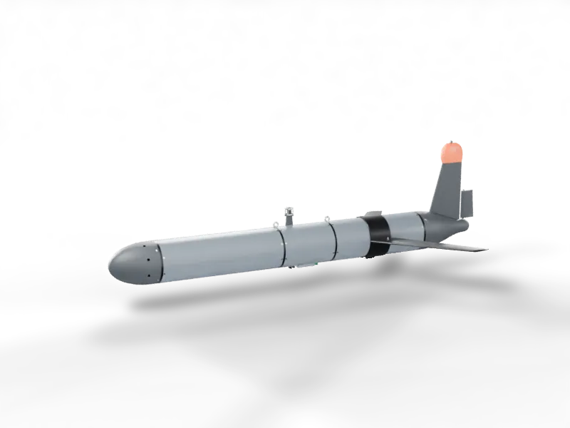
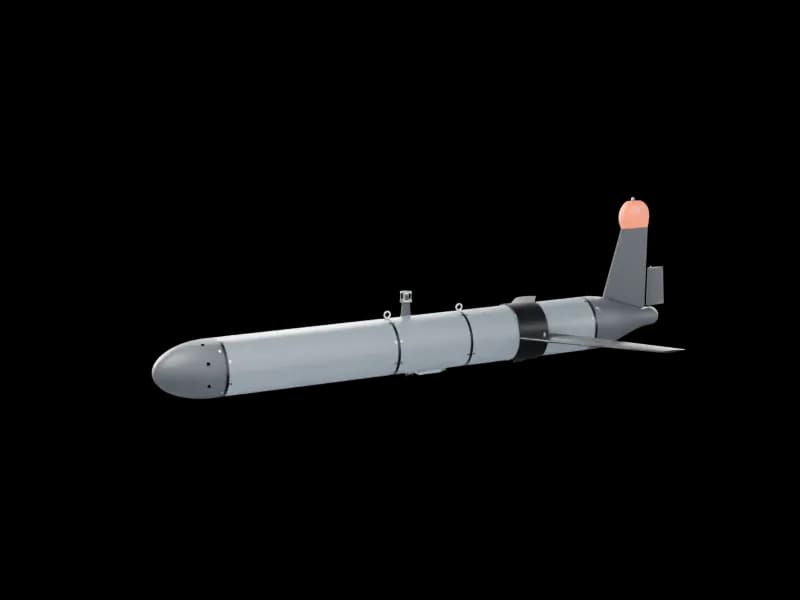
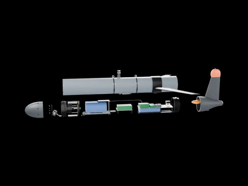
- 01Wing (quick-release pins)
- 02Tail cone, antenna fin and radome
- 03Three hull sections and coupling rings: internals exposed
- 04Nose cone, rudder and external bladder
- 05Buoyancy-engine diaphragm clamp ring
Which parts move
In the cut-away hull only the coloured parts move; everything in light grey is fixed. Each colour is one mechanism: the bright part is what moves, the darker shade is the motor, screw or servo that drives it. Arrows show the direction of motion.
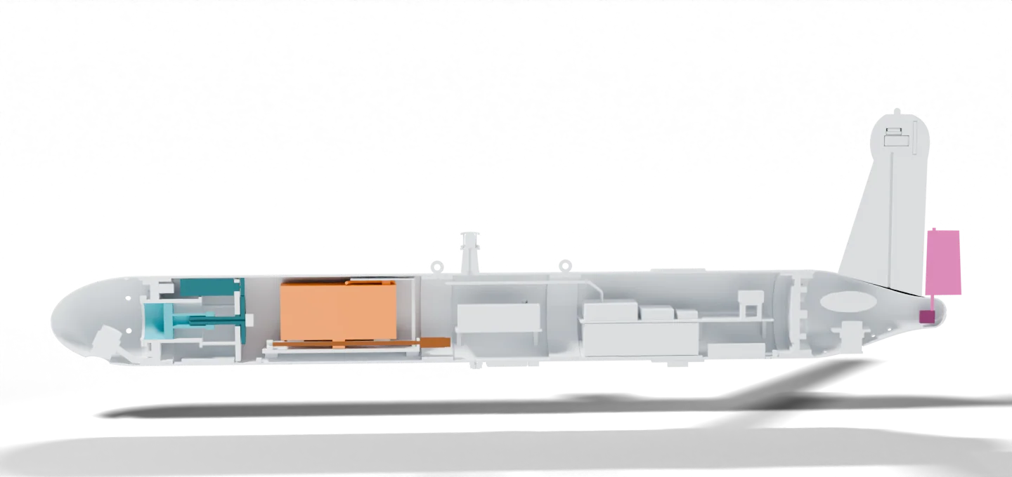
- 1
Pitch battery sled
- Motion
- Slides fore and aft
- Travel / range
- ±35 mm
- What it does
- Shifts the centre of gravity to pitch the nose up or down
- Driven by
- Small motor → lead screw → nut on the carriage; motor encoder for position, limit switches at both ends
- 2
Buoyancy-engine piston
- Motion
- Strokes fore and aft
- Travel / range
- 76 mm stroke
- What it does
- Takes on or expels water to change buoyancy; being in the nose it also helps pitch
- Driven by
- Gear motor → spur gears → ball screw
- 3
Rudder
- Motion
- Swings left and right on its shaft
- Travel / range
- Deflection set by the servo chosen
- What it does
- Steers the heading (turn left or right)
- Driven by
- Oil-filled, pressure-compensated servo driving the rudder shaft directly
See them move
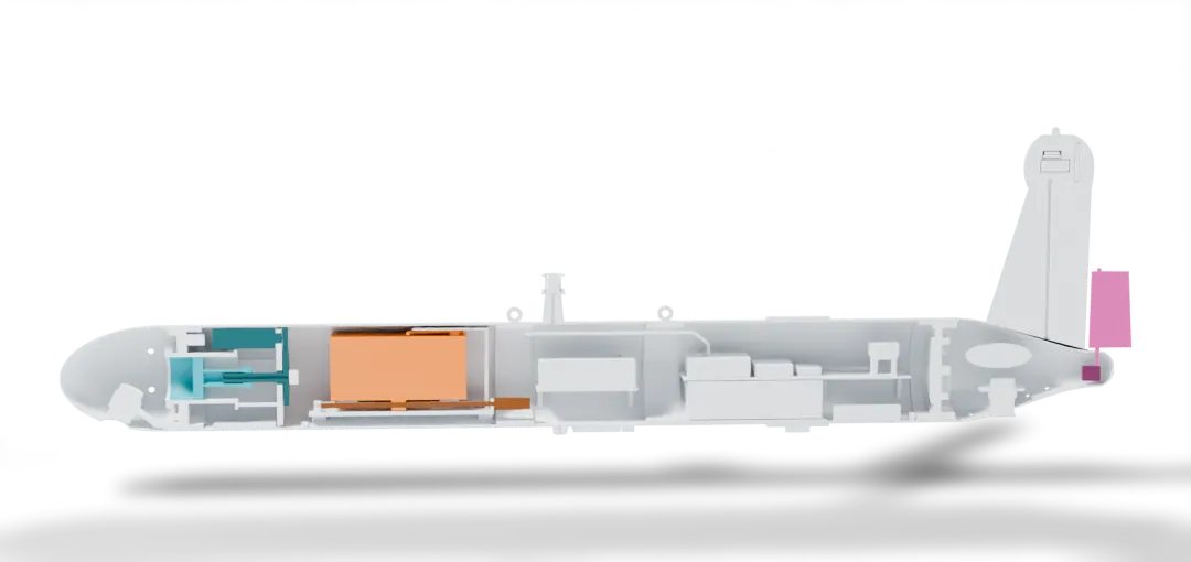
Loading motion frames…
How the battery gets power, what moves it and how its position is known
A moving battery can only be wired with a cable – the point is to let the cable follow the battery without being pulled or kinked, and to know where the battery is at all times.
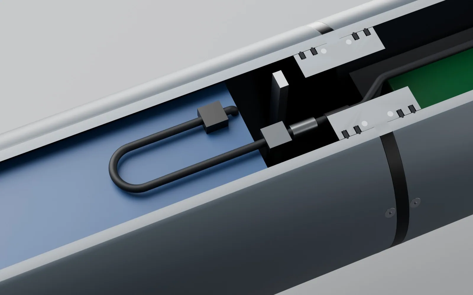
01
Power cable
Exits the top of the battery: a Ø7 mm high-flex silicone cable (2 power cores + battery-management data), laid as a horizontal U-loop above the battery with a 20 mm bend radius (about 6× the cable diameter).
02
Why it does not break
One leg is clamped to the battery and moves with it; the other is clamped to a fixed tray. When the battery travels ±35 mm the bend of the U moves only half as far (±17.5 mm) – the cable rolls rather than being pulled or kinked.
03
Connector and fuse
A disconnect at the fixed end (the battery comes out without cutting wires), followed by an inline fuse; a trunk cable runs along the hull crown through the payload section to the power board in the aft hull.
04
What moves it
A small motor under the sled turns a lead screw; the nut carries the carriage and battery fore and aft. An encoder on the motor rear counts turns, converted to battery position.
05
How it knows the end of travel
A flag on the starboard edge of the carriage passes two slot-type optical switches. At power-up the sled drives to the forward switch to zero itself; at ±32 mm a switch trips and the motor stops before the mechanical end (±35 mm).
G1 buoyancy engine: piston + rolling diaphragm
A glider has no propeller. It dives and climbs by making itself slightly heavier or lighter than seawater, and the wing turns that vertical force into forward glide. G1 carries a piston cylinder in the nose: pull the piston in and seawater enters, displacement shrinks → heavier, it dives; push the piston out and the water is expelled, displacement grows → lighter, it climbs. The weight never changes; only the volume of water displaced does.
Diving glide: net buoyancy −2.4 N
- Depth
- 75 m
- Piston position (from outer end)
- 76 mm
- Displacement change
- −242 cm³
- Net buoyancy
- −2.43 N
- Water load on piston
- 4.8 kN
01
Where 484 cm³ comes from
Piston area π × 45² ≈ 6,362 mm², times the 76 mm stroke ≈ 484 cm³, about one mug.
02
What ±2.4 N means
484 cm³ of seawater weighs about 0.50 kg (4.9 N). Ballast makes the vehicle neutral with the piston at mid-stroke, so half a stroke in makes it 2.4 N heavy and half a stroke out 2.4 N light: only ±0.37% of the 65.8 L displacement. Those 2.4 N give a glide angle of about 18° at 0.26 m/s horizontal; one 150 m profile takes about 1.1 h and covers about 0.9 km.
03
Why a rolling diaphragm
One side of the cylinder is seawater, the other the dry hull. An O-ring slides along the bore; over 66 days and about 1,440 cycles it wears, sticks and seeps. A rolling diaphragm is a fabric-reinforced rubber membrane clamped at the cylinder mouth and attached to the piston; as the piston moves it rolls along the bore instead of sliding, with almost no friction. Sea pressure always exceeds the internal pressure, so the membrane stays pressed onto the piston; the pressure load is carried by the piston, screw and end cap, and the membrane only seals.
04
Why a ball screw with reduction
The piston pushes out against water pressure: about 1.5 MPa and 9.6 kN at 150 m; about 2.0 MPa and 12.8 kN (nearly 1.3 t) at the 200 m design target. A gear motor turns the ball screw through a spur-gear pair; the nut sits in the piston and turns rotation into a high-force linear stroke.
05
How much energy
Pushing the full stroke out at 150 m takes about 1.5 MPa × 484 cm³ ≈ 729 J of work; at an efficiency of 0.45 that is about 1,621 J (0.45 Wh) of electricity, about 2 min at 15 W, or 17% of each cycle's energy; most of the rest is the hotel load of sensors and recording.
06
It also helps with pitch
The cylinder sits in the nose, about 825 mm from the centre of buoyancy: taking on water makes the nose heavy so it pitches down for the dive, and pushing water out lifts it for the climb. On its own it gives about ±19° statically; the moving battery trims the rest.
07
Why G2 and G3 don't use it
The piston load scales with depth: at G2's 1000 m target the same piston would carry about 64 kN, making the screw and end cap heavy, so the deep designs pump oil into an external bladder with a high-pressure pump. A piston engine suits shallow water: simple, efficient and cheap.
08
Still to verify
Coastal seawater density can range from 1.020 to 1.028 kg/L, a buoyancy difference of about 0.53 kg, more than the ±0.25 kg of adjustment, so measure density and re-ballast for each operating area. The 0.45 efficiency is an assumption; bench-test the screw, gears and motor under a 2 MPa load. Confirm the diaphragm's pressure rating, seawater compatibility, flex life and gap against the maker's specification.
How it moves and steers
G1 has no propeller, but it isn't unpowered: buoyancy is the engine and the wing turns vertical force into forward glide. Direction is handled by three other mechanisms: the moving battery for pitch, a low centre of gravity for roll, and a rudder for heading.
Diving glide: nose down about 12°, sliding forward and down on an 18° path
- Pitch
- −12.3°
- Path angle
- −18°
- Heading
- 55°
- Track over ground
- 65°
- Rudder (schematic)
- +20°
- Forward force
- 0.75 N
- Speed
- 0.27 m/s
01
Where the forward force comes from
Resolve the 2.4 N of net buoyancy along the 18° path: the forward component 2.4 × sin 18° ≈ 0.75 N balances drag, and the remaining 2.3 N is carried by wing lift. At about 0.27 m/s the equivalent propulsive power is only about 0.2 W. The energy comes from the battery: the roughly 1,621 J spent pushing water out at the bottom is like towing a sailplane up a hill.
02
The wing works both ways
The wing section is symmetric. Diving, the nose is about 12° down on an 18° path, an angle of attack of about +5.7°; climbing, the nose is up and the angle of attack becomes −5.7°, so lift flips direction and still turns buoyancy into forward speed.
03
Pitch: moving the battery
The 12.9 kg pitch battery rides a lead-screw sled ±35 mm, giving about ±37° of pitch; the nose cylinder adds about ±19° as it takes on water (nose heavy) or pushes it out (nose light). The flight computer keeps trimming the battery against the attitude sensor to hold the path angle.
04
Roll: passively stable
The centre of gravity is about 8.9 mm below the centre of buoyancy, so like a roly-poly toy it rights itself and needs no active roll control.
05
Heading: rudder
The rudder behind the antenna fin is driven directly by an oil-filled, pressure-compensated servo. Water flowing over it pushes the tail aside when it deflects and the nose turns, just like a boat rudder, so it can steer whenever it is gliding. Heading comes from the attitude and heading sensor with a magnetometer, mounted at the rear of the aft section about 1 m from the moving battery to limit magnetic interference.
06
Position: dead reckoning plus surface fixes
GNSS doesn't work underwater, so position is dead-reckoned from heading, depth rate and estimated speed; about every 3.3 h (about 2.8 km) it surfaces for a GNSS fix, sends data by satellite and receives new waypoints. The gap between the estimate and the fix is mostly current; once the depth-averaged current is estimated the vehicle crabs into it (the dashed line on the right is the track pushed off by current). A 1° heading error gives about 48 m of error; an uncorrected 0.10 m/s current about 1,194 m, reduced to about 239 m once the current is estimated.
07
Weak points
Horizontal speed is about 0.26 m/s, so a faster current simply carries it along; it also cannot hold position or fly at constant altitude, which needs thrusters (see G3).
Autonomous navigation and control
G1 is a coastal shallow-water glider (200 m design target): a nose piston changes buoyancy, a sliding battery sets pitch and a rudder steers. It has no thrusters. Below are the control design principles and current simulation results. Everything here is offline simulation; nothing has been tested on hardware or at sea.
Operating modes
With no thrusters, G1 only flies buoyancy-driven profiles. Any mode whose capability is not yet proven stays disabled.
| Mode | How it works | Status |
|---|---|---|
| Survey profiles | Repeated dives and climbs along waypoints, with a GNSS fix at every surfacing; piston, battery and rudder drive and steer. | Closed-loop simulation complete |
| Depth loiter | Drift with the current near a set depth, trimming only with the piston. | Disabled: fine enough piston volume control not yet proven |
| Active station keeping | Actively hold a small area. | Not offered: G1 has no thrusters |
Control architecture
Buoyancy and pitch: the piston sits in the nose
01
Piston sets buoyancy
A 90 mm piston with 76 mm stroke moves about 483 cc in total: pushing out adds buoyancy, pulling in removes it.
02
Nose buoyancy pitches the vehicle
The piston is about 0.8 m ahead of the centre of gravity, so half its stroke alone pitches the vehicle about ±18° statically, more than the roughly 12° a glide needs.
03
The battery trims the remainder
Control feeds the piston-induced pitch forward and the battery corrects only the remainder, so when diving the battery actually moves about 5 mm aft.
04
Sea pressure must not push it back
At 200 m the sea pushes on the piston with about 12.8 kN, in the direction that makes the vehicle heavier. The drive must be non-backdrivable or braked and hold position on power loss.
Navigation and steering
01
Estimator
Uses the G2 18-error-state estimator (copied and re-verified separately). Common pressure-sensor bias is corrected only by surface or independent fixes.
02
The rudder needs water speed
At low water speed the rudder does nothing. G1 judges low speed from pressure-derived vertical speed, attitude and the glide model, so no extra speed sensor is needed.
03
Rudder checks pause at turns
At the bottom turn of each profile the rudder has no authority anyway, so the supervisor pauses rudder tracking and only checks that heading starts to converge once authority returns, avoiding false alarms.
04
Entering from the surface
Starting at rest on the surface, feed-forward brings the attitude into a descending glide; closed-loop control takes over only after attitude and depth change are confirmed several times in a row.
Depth monitoring and safety
01
Rate comparison
The heave rate from pressure is compared with the rate the buoyancy model predicts, using a cumulative sum reset at every independent fix. No drifting double-integrated inertial depth.
02
Model correction at every surfacing
At each surfacing, the requirement that the dive must close up corrects the model rate bias, cutting the model error from about 0.018 to 0.004–0.006 m/s.
03
Recovery on power loss
When main power fails the main computer is treated as gone; only the independently powered recovery chain acts: drop weight, independent surface confirmation by wet/dry and air contact, then a beacon reports position.
04
Still open
On power loss the battery may stop anywhere in its travel. Proving a safe ascent from every position needs hydrodynamic data from a tank test or CFD.
How many dives between two surface fixes
If the pressure sensors drift slowly, the vehicle is deeper than it thinks. The planner sizes the depth margin from the time between the last fix and the bottom of the dive, and only admits as many dives as keep it within the 200 m design depth and clear of the seabed. The chart shows an example with 0.005 m/s vertical current.
These are conditional suggestions from a synthetic model; the 0.005 m/s vertical current is an example, not a measurement.
Status and limits
- Done
- Closed-loop simulation: every admitted normal case passes with zero false alarms and every fault case surfaces safely; hundreds of cases reproduce exactly.
- Not done
- No hardware, bench or sea testing. All sensor errors and hydrodynamic parameters are assumed values, and missions cannot be armed.
- Next
- Full-range power-loss recovery needs tank or CFD data; bench tests of the piston brake, drop weight and surface confirmation.
System layout
Sensors, electronics and batteries are drawn as placeholder envelopes showing size and mounting position; no specific models are named. Swap in real dimensions after selection and recompute.
Navigation
- GNSS antenna + receiverAntenna in the orange radome at the top of the fin; receiver on the aft electronics board
- Attitude and heading sensor (with magnetometer)Rearmost point of the aft section, about 1 m from the moving pitch battery
- Pressure sensor (depth)Dry side of the forward end cap, ported through the cap
- Single-beam altimeterInside the nose cone, tilted 26° forward, window underneath
- Acoustic transponderUnder the tail cone, facing down, for USBL positioning from the mother ship
Comms & recovery
- Satellite and radio antennasIn the radome, separated from GNSS; both modems on the aft electronics board
- Locator beacon, strobeIn and on top of the radome
- External bladder + air pumpBladder in the tail cone, inflated at the surface to lift the antenna fin clear of the water
- Drop weight 0.8 kgUnder the payload section, burn-wire release, dropped to surface in an emergency
- Lifting eyes × 2, leak sensorsOne eye on top of each coupling ring so a two-point sling lifts the hull nearly level; one leak sensor in each of the forward and aft sections
Power
- Pitch battery21700 Li-ion 7S24P (168 cells) 3.06 kWh, 12.9 kg, on the forward sled
- Aft battery7S14P (98 cells) 1.78 kWh, 7.5 kg, on a tray at the bottom of the aft section
- Buoyancy-engine driveGear motor through a spur-gear pair and ball screw pushes the piston; front of the forward section
- Power board, charge/data connectorPower board on the aft electronics board; connector on the aft end cap
Payload
- HydrophoneOn a dorsal mast inside a ring guard, payload section x 760
- CTD sensorStarboard side mount at x 900; the asymmetry is trimmed out with ballast
- Recorder moduleOn the payload-section tray, powered separately from the flight computer
Electrical and data architecture (hardware)
Arrows are data, the heavy line at the bottom is power. Hardware level only: which devices connect to the flight computer or the payload computer, and how power is split; no software or protocols, no specific models.
Navigation sensors
- GNSS
- Attitude & heading (with magnetometer)
- Pressure (depth)
- Altimeter
Buoyancy & attitude
- Buoyancy-engine motor
- Pitch motor
- Rudder servo
Payload
- Recorder module
- Hydrophone → recorder
- CTD → flight computer
Comms & recovery
- Satellite modem
- Radio modem
- Acoustic transponder
- Drop-weight release
- Air pump + external bladder
Mass by system
Total 67.4 kg in air, including batteries and ballast; dots match the colours in the system-layout render
- Structure STR24.2 kg
- Power PWR21.1 kg
- Buoyancy engine BUO6.4 kg
- Ballast BAL4.0 kg
- Attitude control ATT3.8 kg
- Payload PLD2.3 kg
- Navigation NAV1.6 kg
- Control electronics CTL1.6 kg
- Recovery & safety REC1.6 kg
- Comms COM0.9 kg
Energy per dive cycle
One cycle at the endurance operating point (surface → bottom of profile → surface, about 1.1 h), 2.7 Wh in total
- Buoyancy engine0.45 Wh
- Hotel load1.96 Wh
- Attitude adjustment0.08 Wh
- Surface comms0.20 Wh
Renders
Rendered in Blender. Click to enlarge.
Comparing the three
How to choose: many low-cost units listening near shore for a long time → G1; months offshore in deep water with the lowest self-noise → G2; seabed imaging, target search and position reports → G3.
| Item | G1 Shallow-water recon | G2 Deep-water endurance | G3 Hybrid flying wing |
|---|---|---|---|
| Mass in air | 67.4 kg | 66.4 kg | 88.7 kg |
| Displacement | 65.8 L | 64.8 L | 86.5 L |
| Buoyancy-engine full stroke | 484 cm³ | 900 cm³ | 1,126 cm³ |
| Max net buoyancy | ±2.4 N | ±4.5 N | ±5.7 N |
| Battery energy | 4.84 kWh | 6.53 kWh | 3.82 kWh |
| Wing reference area / aspect ratio | 0.18 m² / 7.0 | 0.26 m² / 5.5 | 1.21 m² / 2.6 |
| Max lift-to-drag | 5.8 | 6.4 | 7.0 |
| Max horizontal speed at full buoyancy | 0.32 m/s | 0.45 m/s | 0.34 m/s |
| Endurance operating point | Glide angle 18°, horizontal 0.26 m/s | Glide angle 15°, horizontal 0.32 m/s | Glide angle 15°, horizontal 0.25 m/s |
| Energy per km | 2.9 Wh | 2.8 Wh | 3.4 Wh |
| Estimated endurance | 66 days | 66 days | 43 days |
| Estimated range | 1,330 km | 1,752 km | 896 km |
| Interval between GNSS fixes | 3.3 h, 2.8 km | 6.8 h, 7.5 km | 6.9 h, 6.0 km |
| Pitch (battery + buoyancy engine, static) | ±48° | ±47° | ±54° |
| Hull buckling SF (design target depth) | 1.86 | 1.75 | 2.35 |
| Design target depth (unverified) | 200 m | 1000 m | 300 m |
Method: drag from the ITTC-1957 friction line × form factor × wetted area, plus drag areas of appendages; lift from the wing only (Helmbold–DATCOM), hull lift ignored; the endurance operating point is the net buoyancy and glide angle giving the longest range within buoyancy-engine capacity at a horizontal speed of at least 0.25 m/s; energy covers the buoyancy engine, hotel load, attitude adjustment and surface communications. Power figures are typical for this class of equipment and should be replaced with measured values after selection.
G3 powered mode: speed vs survey line length
With the full payload running (side-scan, DVL, forward-looking sonar, camera and strobes, line arrays, magnetometer) the hotel load is about 32.4 W. Propulsion power rises quickly with speed (drag goes roughly with speed squared), so line length peaks near 0.8 m/s.
Survey line on a full battery (km)
Level flight at neutral buoyancy; overall propulsive efficiency 0.36 (propeller 0.45 × motor and drive 0.80)
| Speed m/s | Drag N | Propulsion W | Total W | Endurance h | Line km |
|---|---|---|---|---|---|
| 0.6 | 5.1 | 8.5 | 40.9 | 74.7 | 161 |
| 0.8 | 8.6 | 19.0 | 51.4 | 59.4 | 171 |
| 1.0 | 12.8 | 35.6 | 68.0 | 44.9 | 162 |
| 1.2 | 17.8 | 59.4 | 91.8 | 33.3 | 144 |
| 1.5 | 26.8 | 111.5 | 143.9 | 21.2 | 115 |
Example mission: after a 80 km round-trip glide transit (about 3.7 days), the remaining energy still covers about 41 h and 147 km of survey line at 1.0 m/s.
Pressure hull (estimates at design target depth)
Cylinder hoop stress, von Mises and Windenburg–Trilling elastic buckling; hemispheres use the classical buckling value × 0.25. Openings, penetrators, end caps and joints are not included and need FEA and pressure testing.
| Design | Section | Material | OD × wall × unsupported length (mm) | Design pressure (MPa) | von Mises (MPa) | Yield SF | Buckling SF |
|---|---|---|---|---|---|---|---|
| G1 | Forward hull | 6061-T6 | Ø220 × 4.5 × 674 | 2.01 | 42 | 6.6 | 1.86 |
| G1 | Payload section | 7075-T6 | Ø220 × 4.5 × 300 | 2.01 | 42 | 12.1 | 4.47 |
| G1 | Aft hull | 6061-T6 | Ø220 × 4.5 × 560 | 2.01 | 42 | 6.6 | 2.25 |
| G2 | Pressure tube (between ring frames) | 7075-T6 | Ø230 × 8.0 × 608 | 10.06 | 121 | 4.2 | 1.75 |
| G2 | Hemispherical end cap | 7075-T6 | Ø230 × 7.0 (hemisphere) | 10.06 | 80 | 6.3 | 8.59 |
| G3 | Pressure hull (between end caps) | 6061-T6 | Ø212 × 6.0 × 780 | 3.02 | 45 | 6.2 | 2.35 |
Open items and next steps
- Hydrodynamics: Lift-to-drag and speed are hand estimates by component. Run CFD or a towing tank to get lift, drag and pitching-moment coefficients, then tune wing position and area.
- Pressure: FEA on end caps, penetrators, joints and V-band clamps, then a pressure test above the design target. No depth is stated until the report is in.
- Buoyancy engine: Bench-test efficiency, flow and power of the piston (G1) and high-pressure pump (G2, G3) at design pressure; the estimates assume 0.40–0.45.
- Trim: Weigh in a tank, measure the centre of gravity, adjust ballast; measure seawater density in the operating area. Recompute once placeholders are replaced with real modules and the ballast is solved again.
- Magnetic interference and self-noise: Calibrate the heading sensor in the assembled vehicle; measure the effect of battery motion and rotation on heading, and of thrusters and oil pumps on the hydrophones.
- Battery safety: Thermal runaway and venting of lithium cells in a sealed hull, and transport rules for primary cells, are handled at selection.
All concept designs, not manufacturing drawings; depths are design targets and do not indicate a pressure rating before pressure testing.